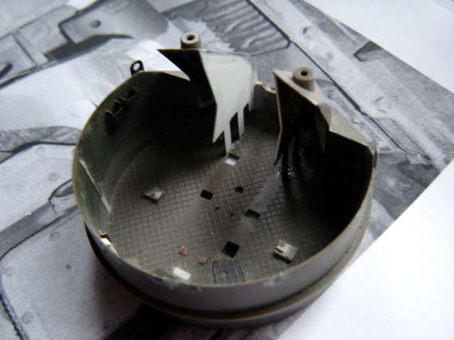
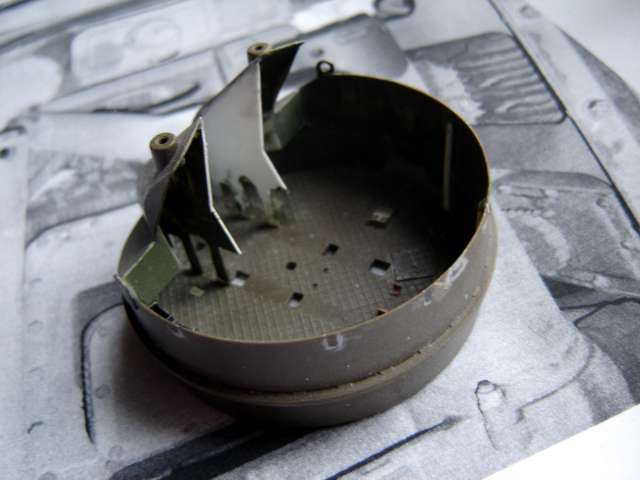
As the basic work on the hull is done, I went on to build the vehicle's main armament and its mount. After taking a closer look at the kit-supplied parts, in comparison the hull was done with high fidelity and precision. First thing I did was to add the armored shields in the front of the main gun mount, and filled the cutouts on the brim, as per instructions for the Eduard detail set. After thinking about it, I gave up the kit-supplied machine gun mounts. After the fillings of the cutouts dried thoroughly I decided to thin the walls of the mount, as they seemed unproportionally thick. I did that with a motor tool, this operation requiring much caution. I also manufactured portions of front armor shields on the inside of the turret and primer-filled the inside surface. Additionally I glued-on the reinforcements on the inner side of the turret wall. As the work on the mount progressed, collected more and more documentation and a moment came, when I couldn't live with the vertical armor portions in the front of the mount. The kit parts are too thick and they miss the openings in their lower area. Because of this I decided to conduct the drastic operation and I cut the mentioned parts out using a motor tool, then I fabricated a replacement out of styrene sheet. The result of work mentioned above can be seen on the following photos:
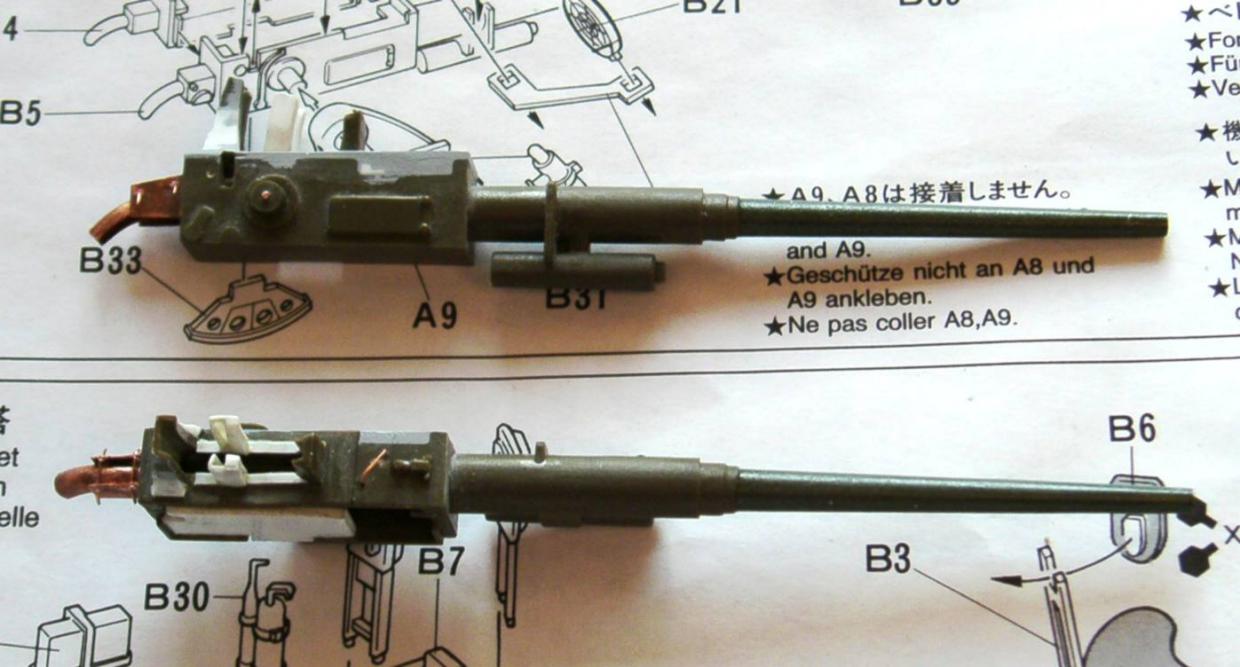
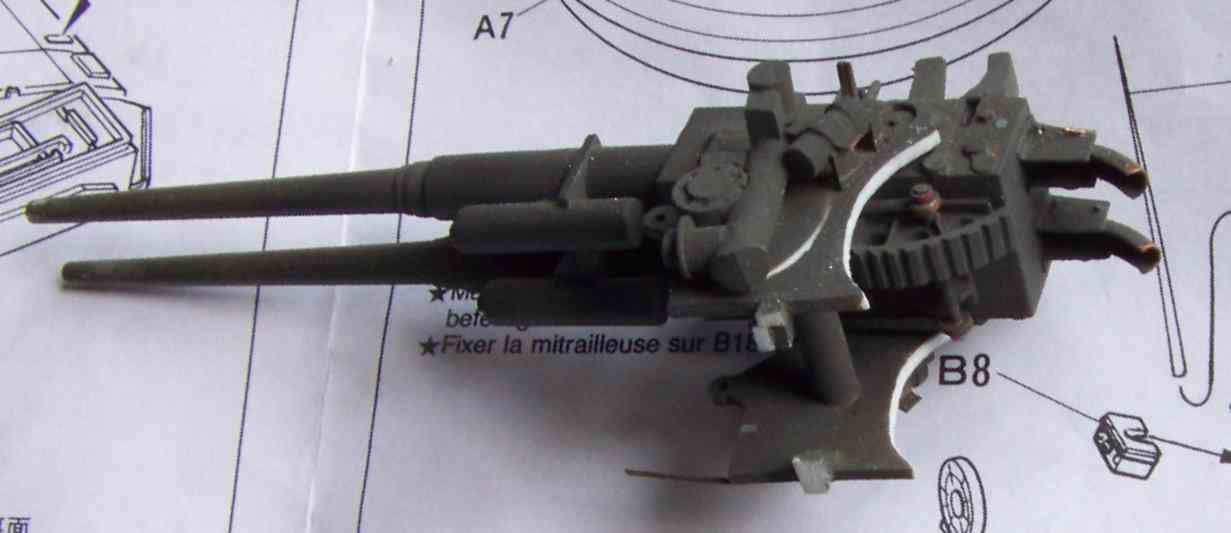
Next thing to do was the main armament - double 40 mm gun. It consists of two receivers - halves with one barrel each, and a top lid with computing sight assembly. Because the kit-supplied parts were poorly detailed, I decided to heavily modify this subassembly in my model. I cut the receivers' lid in two and removed and saved the computing sight portion. From then on I could work on each half of the gun assembly separately. I glued and filled each receiver and fabricated two gun muzzles out of brass tube. I decided to depict guns without flash suppressors, as it is often seen on the photos from Vietnam. I then detailed the automatic ammo feeders on top of the guns, and fabricated the chutes for empty shell cases on the rear of the guns out of copper sheet metal, together with the recoil gauges. Last thing to do was correcting minor details on top of the receivers. After this was done, I glued the guns together to finish the subassembly, which is shown on the photos below before and after the gluing:

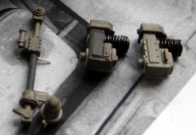
Building the guns allowed me to go on with the mount, and, on the other hand, with the computing sight assembly. Analysis of original's photos showed, that it would be of advantage to build the mount from scratch. I fabricated the halves out of 1mm sheet styrene. Firing solenoids are mounted on them, which I also scratchbuilt. Left to do were the traverse (right side) and elevation (left side) motors and gear cases. The traverse and elevation oil gear, mounted in front of the turret are too far in front as per kit, but after relocation should look good. The twin gun in the mount can be seen in the following photo:

The photo shows the firing solenoid on the gun mount. The traverse mechanism normally mounted in front of it is yet to be installed. Additionally the mount will also be fitted with the twin equilibrator located under the recoil mechanisms of the guns. The equilibrator will be well visible after elevating the guns.
Additionally a lot of work will be required to outfit the turret. Some of the fittings are contained in the photoetched details set from Eduard, however many of them will have to be built from scratch. The hardest, in my opinion would be the bottom chutes for empty shell casings. I built them also of thin copper sheet metal ad the effect is quite good. The construction holding them in place is yet to be done. Crew seats, two foldable and two fixed also will have to be added, along with gun racks, ammo box holders and the likes.
The computing sight assembly uses some portion of the kit's parts, but it will be greatly enhanced with photoetched peep sights. I decided to scratchbuild the mounting of the sight assembly to the 40 mm guns' receivers. First result of work on the sight assembly and oil gear after conversion from kit parts can be seen on the following photo:
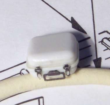
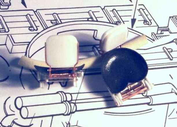
Continuing work on the computing sight I decided to further modify the "ball" (the sight's computing unit). Using this assembly one of the Duster's crew members sets the target's parameters, such as its speed or heading. I fabricated the miniature of the "ball" out of styrene sheet and turned aluminum, I also used a part from Eduard's photoetched set. The finished subassembly can be seen on the photos below:


I had to modify the remainder of the computing sight accordingly, as seen below:

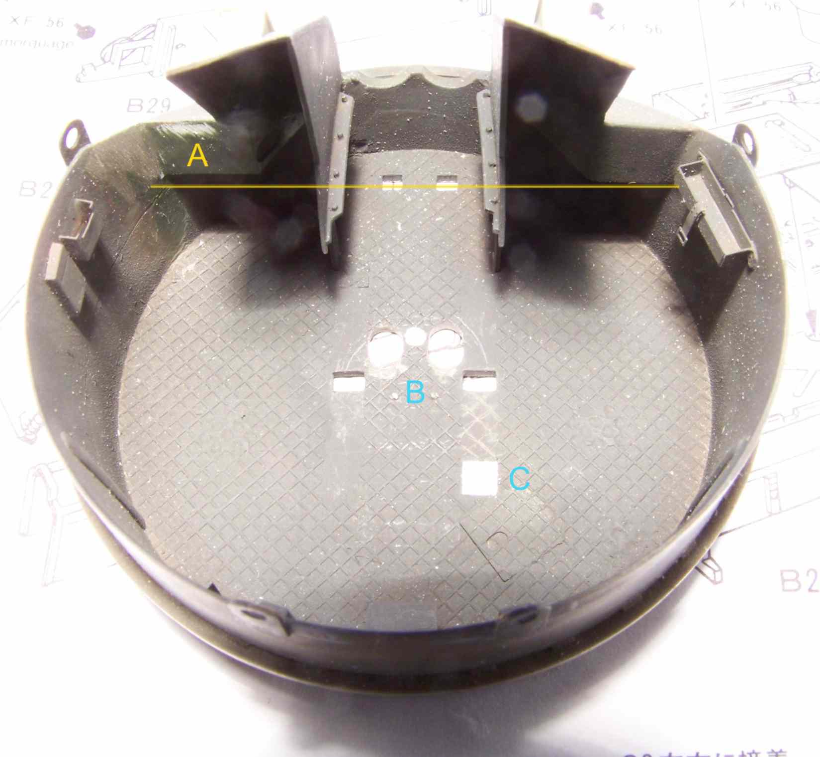
As my collection of reference material grew, I decided to further modify the turret, as shown:
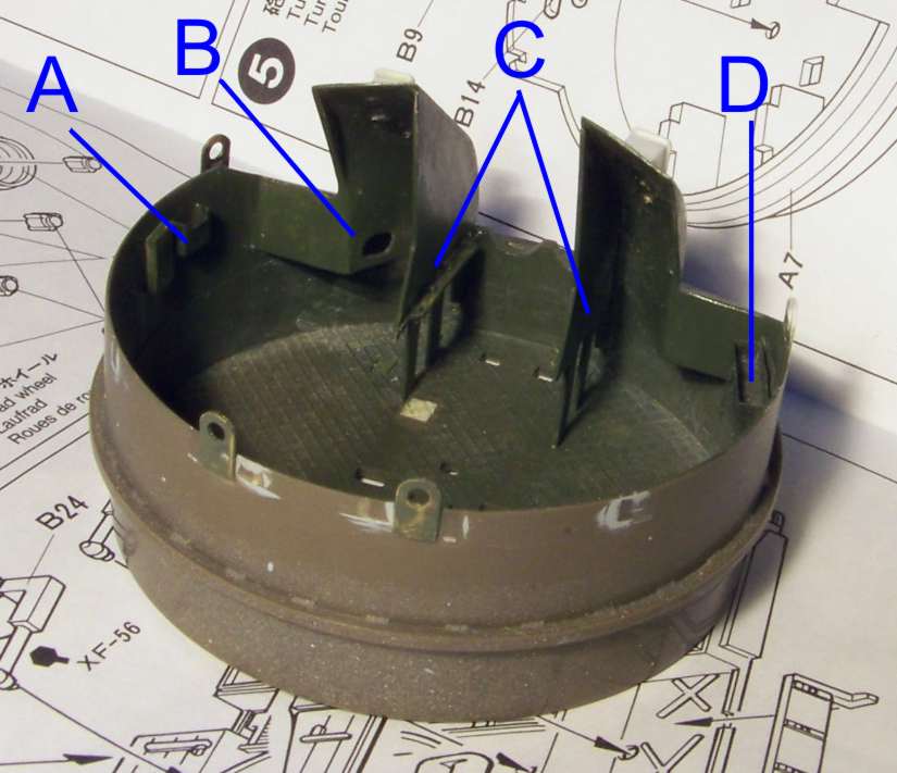
In the photo above, the following modifications are shown: A - small accessories compartment made out of photoetched parts, B - additional sheet metal, absent in the original kit, C - vertical armor plates replacing incorrect kit's parts and D - first aid kit bracket made of photoetched parts. I also made new antenna bases and added lifting eyes on the front armor plates, as shown in the photo below:
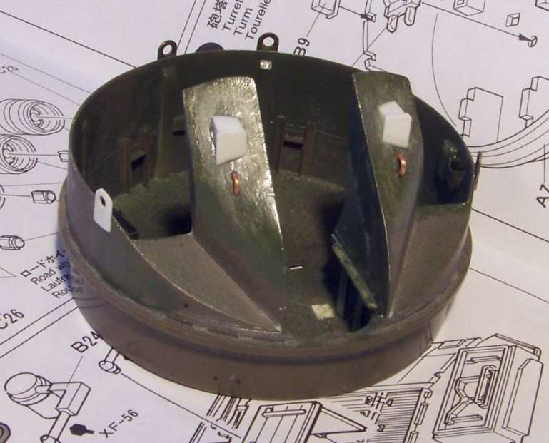
The reference I have indicates that it's necessary to fabricate many small details of turret equipment, that are either absent or incorrectly depicted/overly simplified in the original kit. The materials I used were sheet styrene of different gauges, different gauges copper wire and copper sheet and also photoetched parts of the Eduard kit. The following photos show the results of my work:

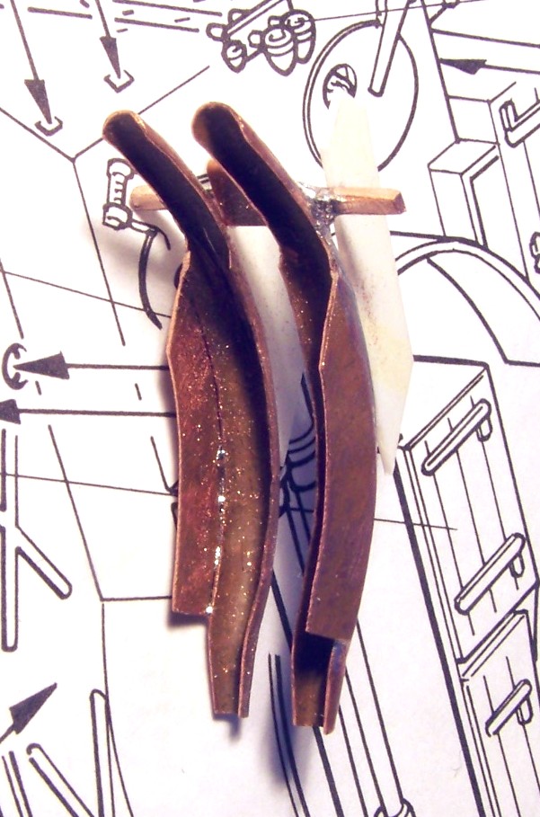
One of the elements of the mount's equipment, which the model lacks most obviously and at the same time an element which is most difficult to build are the chutes used to conduct the spent casings from the guns' breeches to under the guns and further under the vehicle. I had a hard time thinking about how to build this detail; finally I decided to try my luck at sheet metal work using 0,2mm copper. First I bent two straight gutters, which I later bent. I used flat pliers (without "teeth" so as to save the surface of the sheet metal) for this work, I used a 3mm drill bit to form the straight pieces and then I bent them using a hook from a clothes hanger as a form. After some tedious fitting the chutes got their final shape with narrower ends, I soldered the side sheet metal to them and then soldered them together. Lastly I added the supports. The completed assembly, which took me several hours of work, can be seen on the photo below:
While fitting the chutes it become obvious, that my scratchbuilt main armament base also needs reworking. It was no easy decision to make, but after reworking the guns' base looks like that:
This modification necessitated filling one more opening in the main armament mount. Now this part looks like on the following photo:
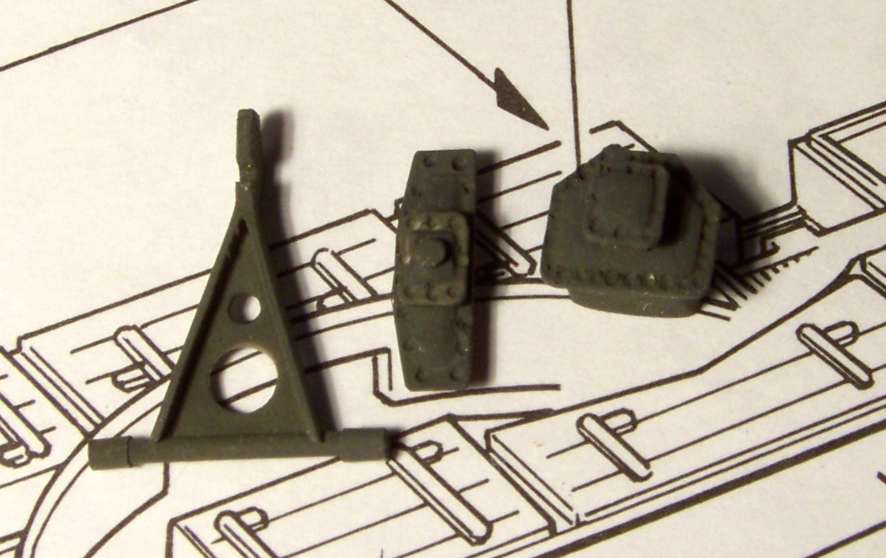
While at it I also made one more modification, the arrow points to the place, where I moved a vertical sheet metal forward, to depict the asymmetry that was characteristic of the M42. The markings of the above photo can be explained as follows: A - sheet metal moved forward, B - openings for extraction of the spent round casings, C - filled opening in the main armament mount's base.
